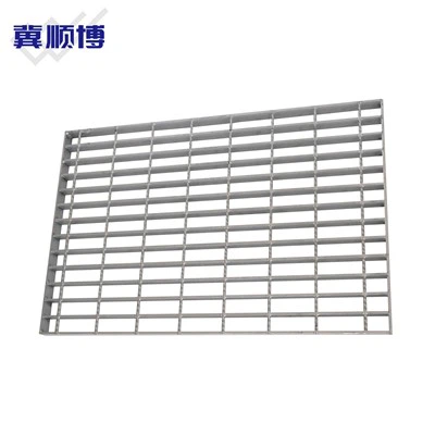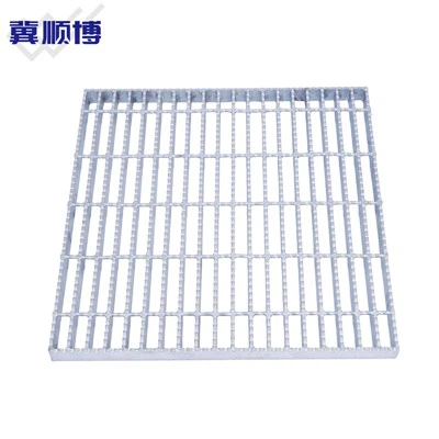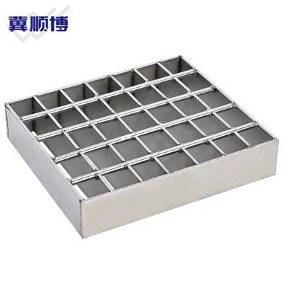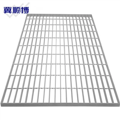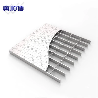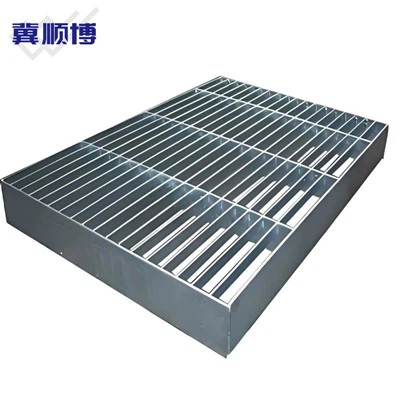
A grating drawing can look simple until the bearing-bar spacing appears in several versions. The spacing describes the distance between the load-carrying flat bars, and changing it affects panel weight, open area, and the way the surface feels underfoot. It should be read together with the support span rather than treated as a stand-alone number. 30mm bearing-bar spacing is described as a common industrial option.
A 40mm series is lighter and is used where spans are shorter. The 60mm series, paired with 50mm cross bars, leaves a more open surface and is used in selected mining or processing areas. These values help explain why two pieces of galvanized steel grating may look similar but serve different jobs. Before ordering, check which direction the bearing bars run. They should span between the supports.
Then confirm panel length, width, support distance, expected loading, and whether the surface should be plain or serrated. Edge banding and fixing clips should also appear on the drawing when needed. For galvanized steel grating, the zinc treatment is only one part of the specification. The bar size and spacing still determine how the panel works structurally.
Reading those details makes it easier to compare options and reduces the chance of receiving a panel that fits the opening but not the support arrangement. Keep the support direction identifiable.